APEL Studio Tutorial
In this tutorial we will use the CheckSignals.APEL script with the Atomic Training Platform (ATP). The script will then check that all eight signals are connected correctly between two devices on the JTAG Scan Chain.
This first step for the script is to define the scan chain for the ATP
CHAIN ATmega164P.TQFP.AVRDEVICE, EPM240T100.TQFP100.MAIN, EPM3032AT44.TQFP44.SUPPORT
If we look at AtMega164P in the schematic we can see that Port A is connected from Pin 37 to Pin 30 with Pin 37 being the LSB.
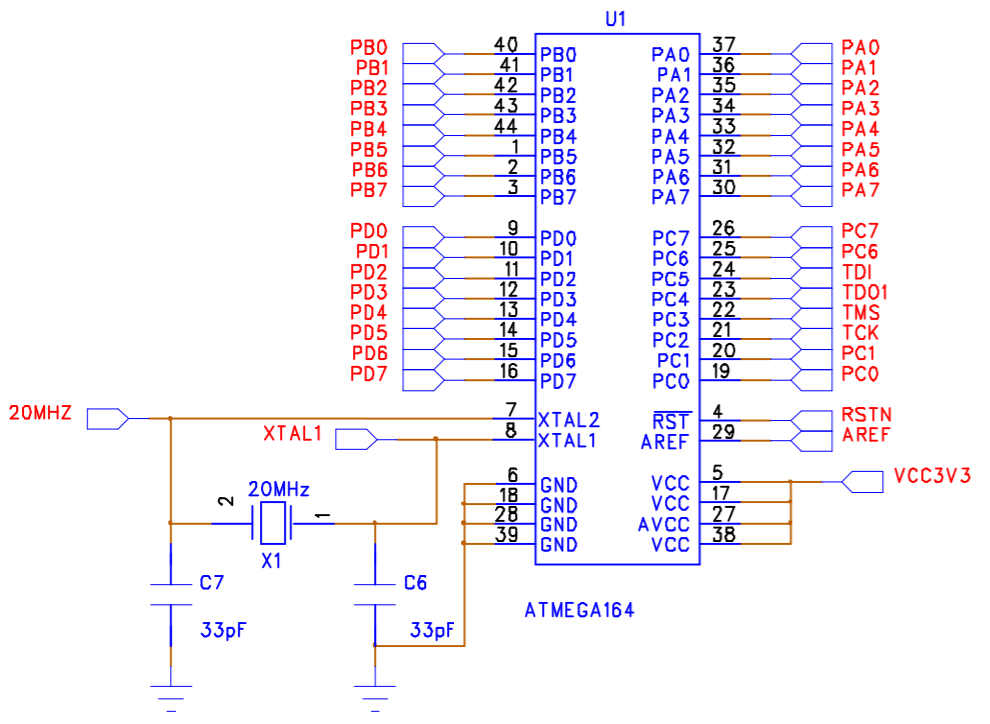
We can define a bus as follows:
BUS PA_ATMEGA = {AVRDEVICE.PA7, AVRDEVICE.PA6, AVRDEVICE.PA5, AVRDEVICE.PA4, AVRDEVICE.PA3, AVRDEVICE.PA2, AVRDEVICE.PA1, AVRDEVICE.PA0}
This bus is also connected to an EPM3032 pins 10,12,13,14,15,18,21 and 20.
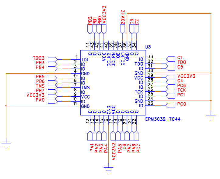
We can define a bus as follows:
BUS PA_EPM3032 = {SUPPORT.IO20,SUPPORT.IO21,SUPPORT.IO18,SUPPORT.IO15,SUPPORT.IO14, SUPPORT.IO13,SUPPORT.IO12,SUPPORT.IO10}
We then define a function that will test the bus connections and call that function to test the buses connections.
Running and Stepping
APEL studio allows APEL script to be debugged using the following keys
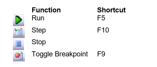
Inserting a Breakpoint
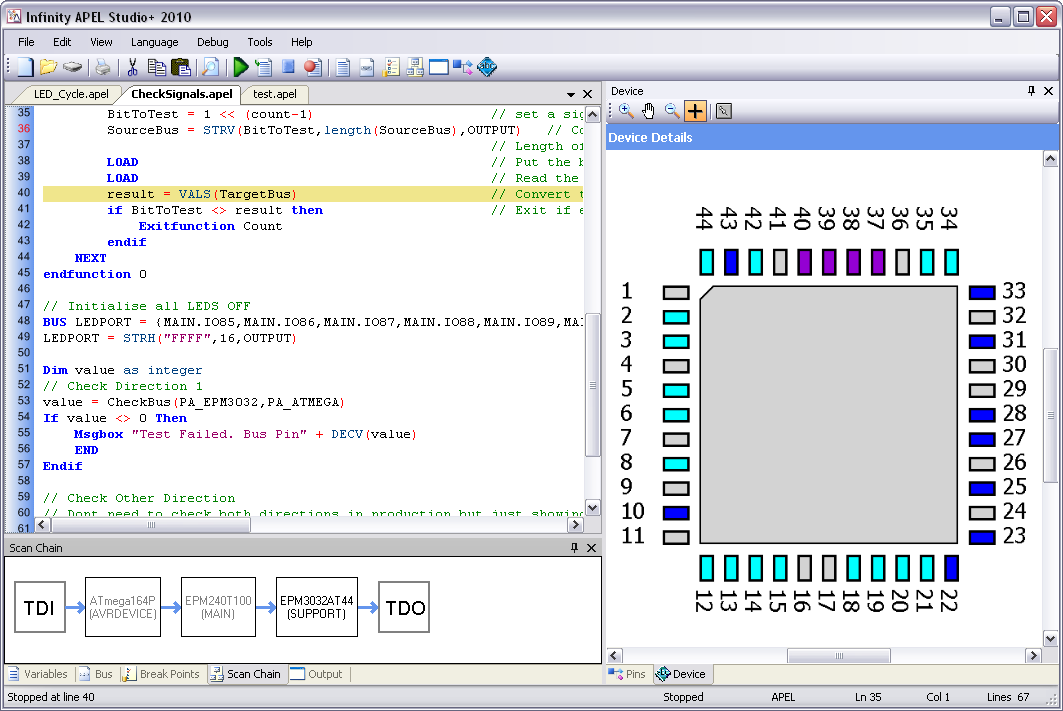
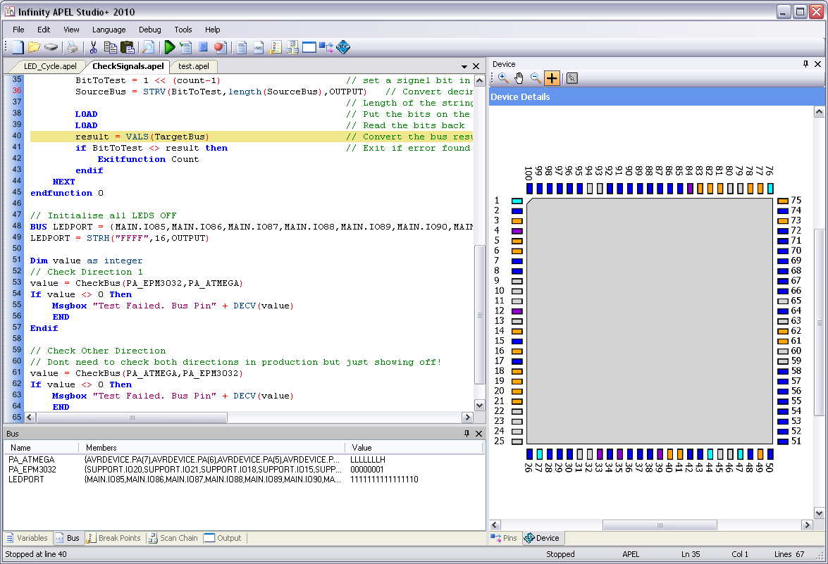
To insert a breakpoint at line 36 we place the cursor at line 36 and them press F9 (or click on the Toggle Breakpoint button).
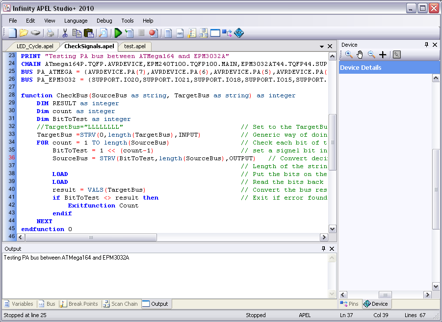
Pressing F5 (or clicking on the Run button) will cause the script to run until line 36 is hit. Make sure that a AP-114 is connected correctly to both your PC and Training board before running the script.
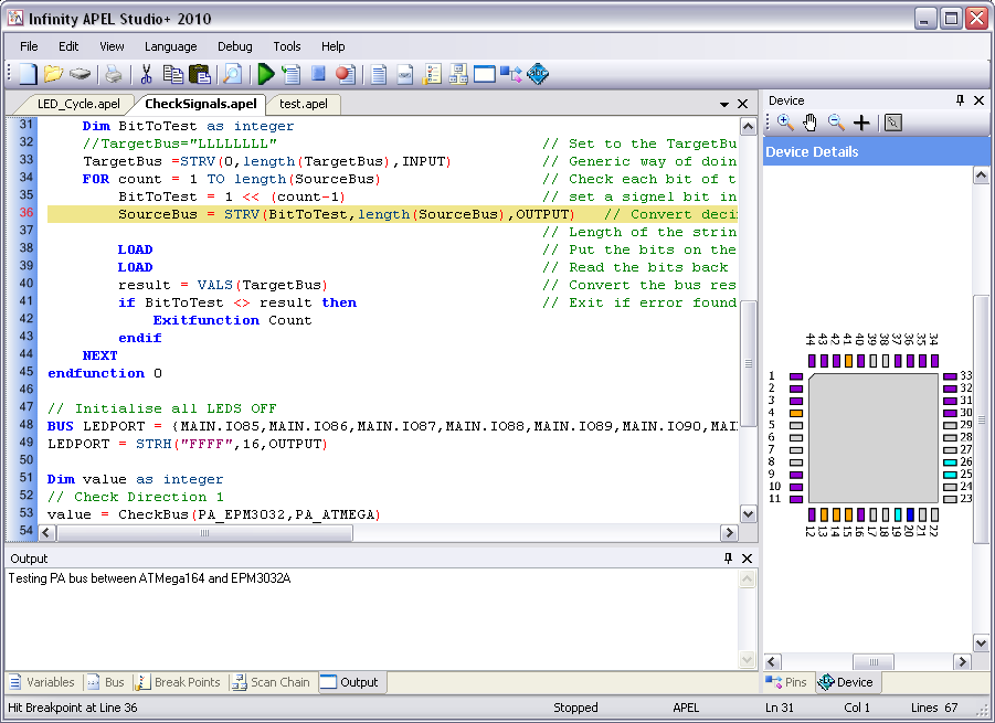
We can now see that line 36 is highlighted and the script has stopped execution. Select the bus Window and we can watch the bus value changing as we step over each line.
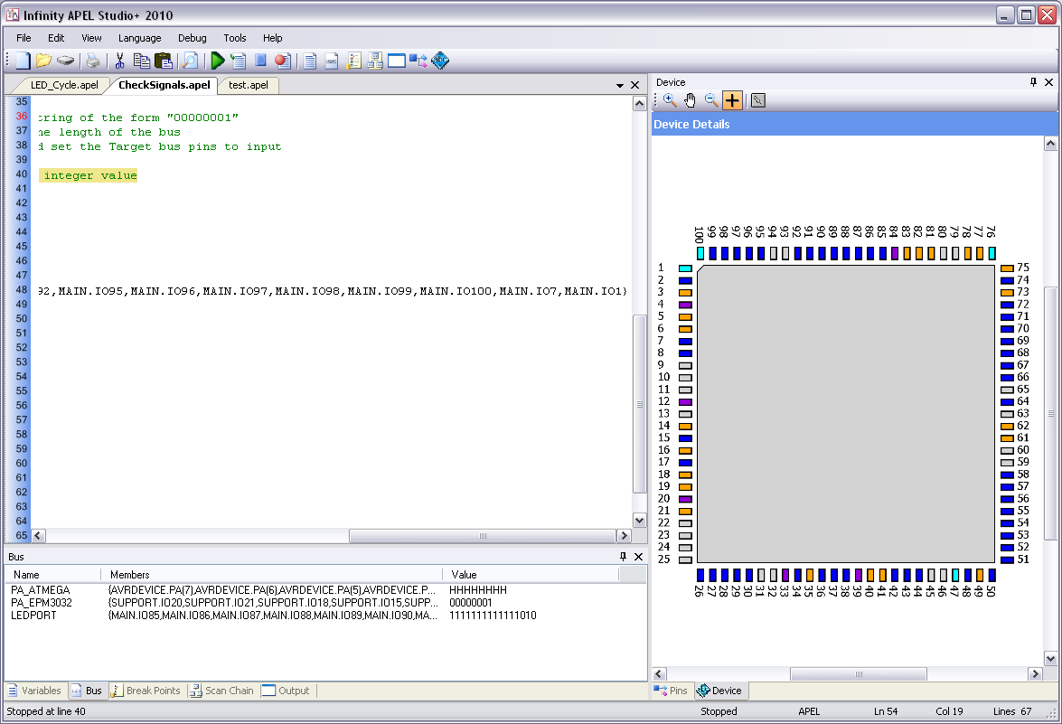
Press F10 to move to the first LOAD command and then press F10 again to move to the second LOAD command and we see the following. SourceBus (PA_EPM3032) still has the value 00000001 assigned to it on line 36. TargetBus (PA_ATMEGA) shows all inputs high. This means that the Output Drivers for this bus have been correctly switched off during the first LOAD command. LEDPORT has all bits set to 1 therefore all of the LEDS are off.
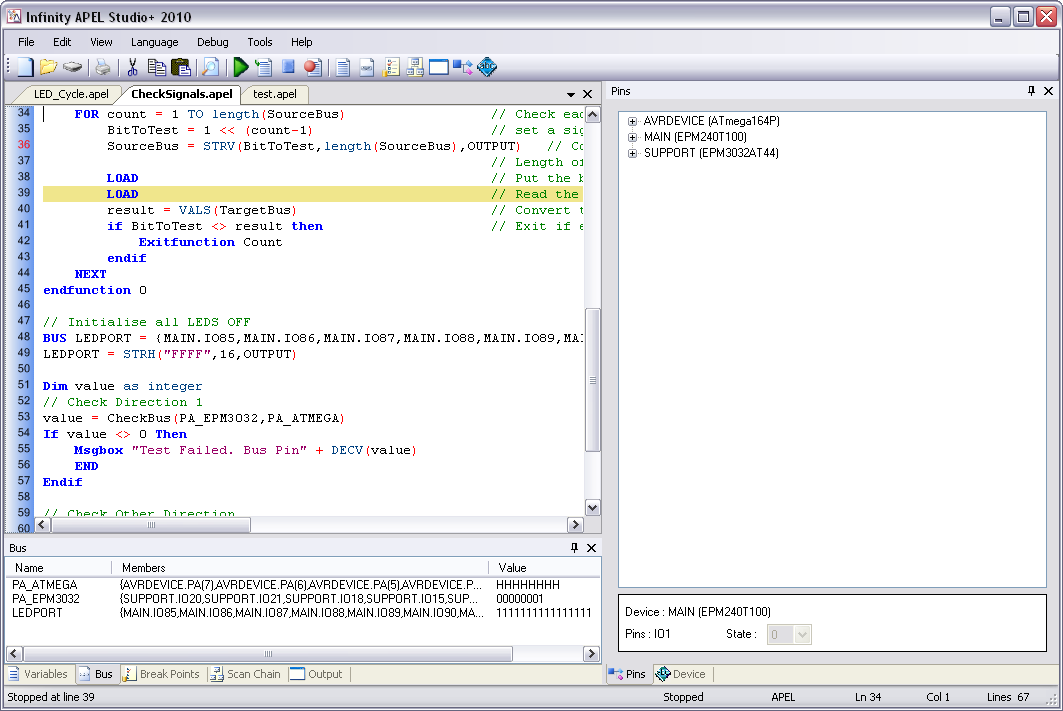
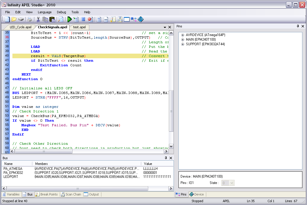
We now press F10 again to execute the second LOAD command. We can now see that PA_ATMEGA now has the value LLLLLLLH which shows that the output signals from the PA_EPM3032 bus have now been sampled correctly.
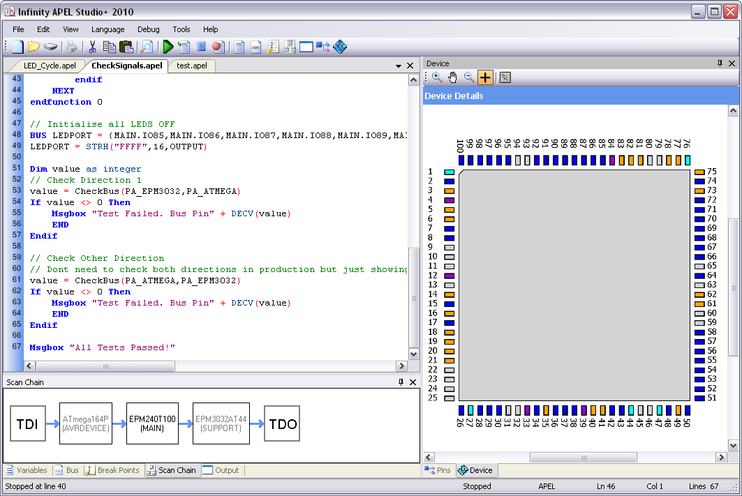
We can also check this by viewing each device in the scan chain. Click on the ScanChain Window and select the first device (ATMEGA164P). Here we can see that pin 37 is a High Input and pin 36 to 30 are low inputs.
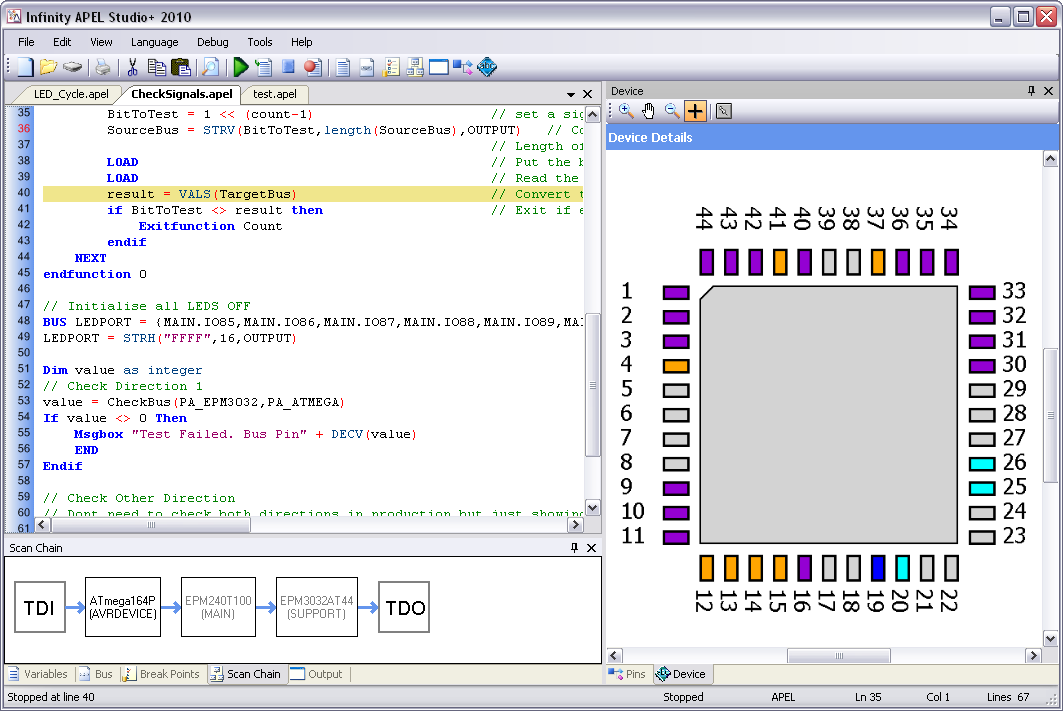
We can do the same thing by clicking in the third device (EPM3032AT44). Here we can see that pin 10 is a High Output and that all other pins on the bus are low.
Editing a Pin on a Device
At this point we can take the opportunity to toggle one of the pins. We select the second device in the scan chain. From the schematic we know that that the first LED is on Pin1. This pin is currently a high output (which switches the LED off). To change the pin select the Cross tool from the device toolbar and click on pin 1.
This takes you to the Pins Window. Here we can see that the pin is IO1 and is currently set to a 1. To change this, select O from this list.
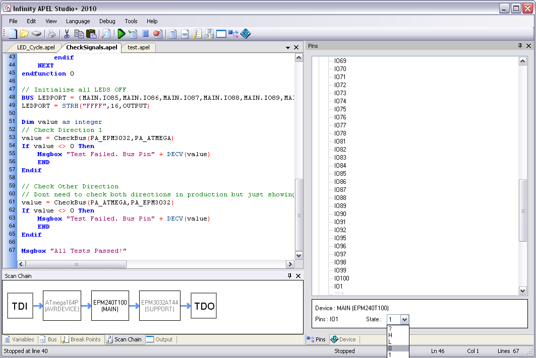
At this point, the Device window will appear and Pin 1 will change to a Low Output. The first LED will also illuminate.
Click on the Bus window and this will confirm that the bottom bit of the bus is set to zero.
Editing a Bus
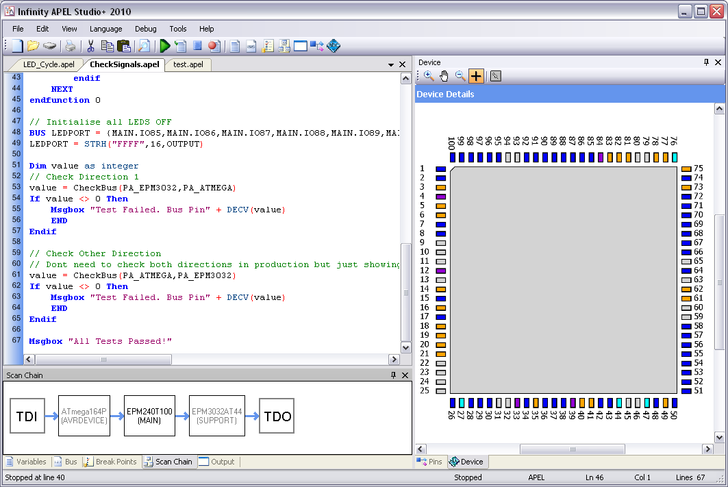
Now that the bottom bit of the bus is set Low. We can easily edit other pins on the bus by editing the Bus Value directly. Click on the Value Part the LEDPORT on the Bus Window. In this example we have set bit to zero.

Below we can see the effect of changing the bus. The third bit is defined in our Bus statement as MAIN.IO100. We can now see that Pin 100 has also gone low and a second LED is lit on our board.
Editing a Variable
We have now stepped down to line 41 and have variables Result and BitToTest both set to 1.
We can edit on of these variables by clicking on the Value section of the Variables window.
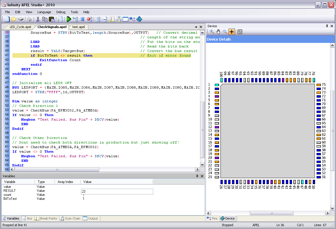
We can now edit the value. In this case we have entered 23.
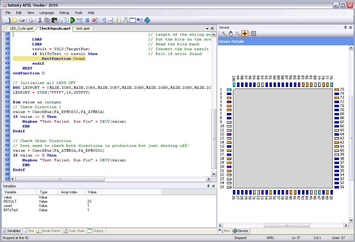
If we now step to the next line we can see that the If condition has failed and the script is about to exit the function.
Viewing a Value in an Array
In this example we have created an Array of integers called Address. At line nine we have set the eighth (zero based array) element to 54, but this value is not displayed in the Variables window. This is because the Array index is set to zero so the value for Address[0] is not initialised.
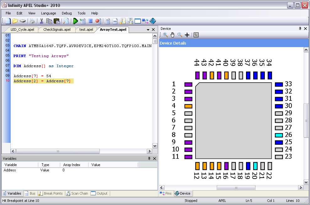
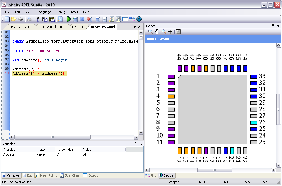
To view the array value, set the Array Index to 7 by clicking on the array index value.

Now we can see that the element does indeed have the value 54.
Building an Executable with APEL Compiler
The APEL compiler (available with APEL STUDIO+) allows scripts to be compiled into executables. These executables have the following features
- They are portable and can be installed onto other computers
- They protect source code and cannot be edited
- They do not require the USB Dongle to be fitted.
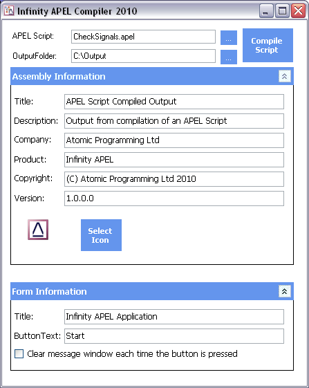
Running the Compiler
The compiler can be run from the Atomic Programming/APEL menu and with start with the image below.
|
|
|
Compiling
After compilation there will be a set of files in the output folder. The main executable will have the same name as the script but with a .exe extension.
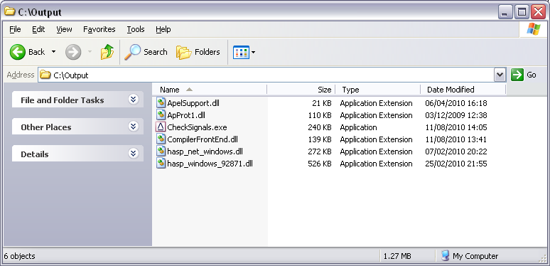
Associated Files
There will be other files in the folder with the executable. All of these will be needed to deploy the application on another system. Simply zip the file up or create an install utility (using NSIS or similar) that includes all of these files.
Infinity Database
APEL uses the Infinity Database. See Database for more information