Infinity Database
The Infinity Database is a list of parts that have been created by importing BSDL files into the database. These parts are using in all Infinity Suite Modules. The library can be edited from Infinity APEL (Library option in the File Menu) or from Infinity Scan (Device Library in the Tools Menu or the Library button in the Scan Chain Window)
Library Editor allows both parts and symbols that are stored within the Library to be edited or to create new parts. It also allows parts to be imported using readily available BSDL files.
NOTE: In the Infinity Database ‘packages’ and ‘symbols’ have a different meaning. A Package is the name of the package listed for a particular device in its BSDL file (For example a device have 3 packages listed (DIP, PLCC TQFP). Symbols are the graphical representation of a package. In this case only a DIP symbol and a QFP symbol are required. The DIP package will use the DIP symbol and the TQFP and PLCC packages will use the QFP symbol. From within SCAN and APEL only the package will be used as listed in the BSDL file.
The database is common to all users on the machine and is keep in the “All Users” Windows profile. On Windows 7, for example, this means that the database is stored in “C:\Users\All Users\Atomic Programming\Infinity\JTAG Library”. The Parts.Lib file contains a list of all of the devices in the database and how the packages are mapped onto symbols files. Inside the Parts folder is a list of .part files. These contains the details of the boundary scan chain for each device. The symbols are stored in the Packages folder and have a .package extension.
From within the Part Properties window, you can:
|
|
|
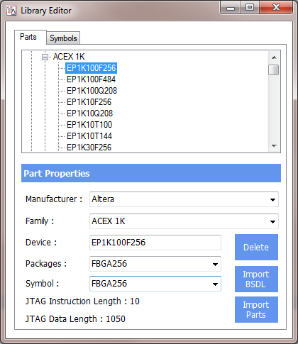
All this is done by pressing Enter in the correct Combo box once you have typed in the new selection. New parts can also be imported using BSDL files.
Clicking on the Symbols tab allows you to edit and add new symbols, using the Symbol Editor. You can also see have many parts in the library are using each symbol.
Adding a New Part
When a device is connected in the JTAG scan chain that does not exist in the device library, a new device can be created.
From the Library Editor, select the Parts tab, and click on IMPORT BSDL. The BSDL files will have a BSDL or BSD file extension. Both can be used without name changes for importing.
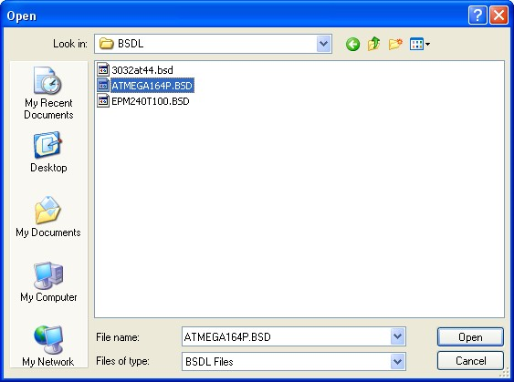
The following screen in shown following the import function:
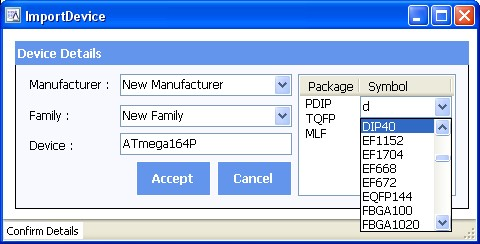
The manufacturer and family information is not included in the BSD file so these will default to unspecified. Simply select the Manufacturer and Family from the drop down menus, or type in the correct name as shown below. You will also need to select the correct symbol from the list of available symbols for each package on the device. If the symbol does not exist then you will need to create it using the Symbol Editor. Currently boundary cell types BC_0 to BC_10 (and the LV counterparts LV_BC_0 to LV_BC_10) are supported.
Click Accept to complete the Import.
Symbol Editor
The symbol editor is selected by selecting the Symbols tab.
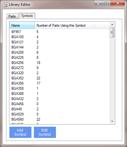
The Symbol Editor is then launched by either double-clicking on the symbol name you want to edit, or by pressing Add Symbol. The highlighted selection is used as a base for the new symbol. If no symbol is highlighted, this will default to the symbol at Index 1 (in this case BF957).
Please note that it is strongly recommended that a symbol is selected that most resembles the device you wish to add as this will save a large amount of time.
You can also see have many parts are using any listed symbol. Should any symbol not have any parts associated with it, then it can be deleted simply be highlighting it, and then pressing the Delete key
The Symbol Editor is divided into sub-windows.
Symbol Details
The Details section allow you to
a) Change the name of the symbol (essential for all new symbols)
b) Change the size of the margin around the device as it is displayed.
Pin Tab
This is the most complex part of the symbol design - which it is why it is recommended to use the symbol that is most similar to the part you are creating. After changing any setting, click on Update to see the result of the change to the symbol.
There are three Block types - round, horizontal and vertical. The round ones are used in BGA devices, and the horizontal/vertical ones used in PLCC and TQFP devices.
It is probably easier to understand if we use examples.
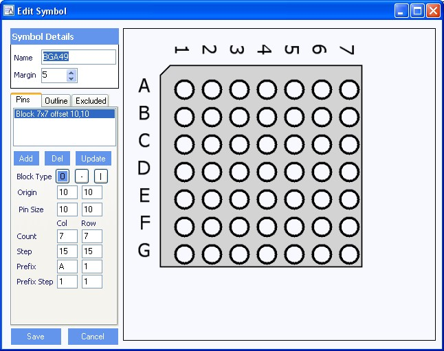
Example 1: BGA49
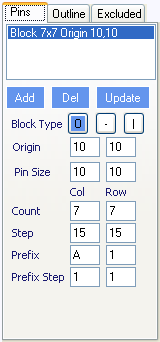 |
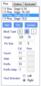
Block Type: Circle (BGA pins) Origin: This is the location of the top-left pin, measured in pixels from the outline Pin Size: The size of the pin, in pixels. Change the first pins size value to 20 and then click update, try setting the second value to 20 and click update. Set them back to 10 when done. For circle pins, both the 'Col' and 'Row' data is used By reducing the step and pin sizes, it is possible to get a greater number of pins into the same outline. For example, change the count to 8 and 8, reduce the pin size to 6 & 6, and the step size to 12 & 12, then click Update. Prefix: this the name of the first pin. Prefix Step: tells the prefix how to change value for each pin. If it is a decimal digit, setting this to '1' counts up by 1 and '-1' counts down by 1. For ASCII characters this value has no effect. The order is predefined with certain characters missing (I,O,S,X,Z) - try changing Prefix (Row) to 7 and the prefix Step(row) to -1 |
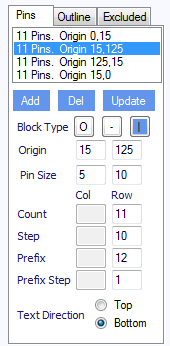
Example 2: TQFP44
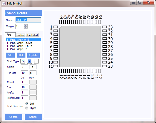
Block Type: Rows are vertical blocks. Columns are horizontal blocks
There are four groups of pins (called blocks for this symbol). The first group has a horizontal block type so the 'row' data is not used. The other three blocks are shown below. Horizontal groups have no 'col' data.
 |
 |
|
For each block the origin and pin size is as per Example 1 above. Try selecting the first block and then changing the pins size from 10x5 to 20x5 and then click update. For this first group you can see there are 11 pins. Again the step determines the distance between the pins. The prefix is the first number and this number is counting up on the first block. If we click on the third block, we will see that the Prefix is 33 and it counts down.
The text direction is the left/right alignment of the text next to the horizontal pins (in columns). This tells you whether the pin number should go left or right of the pin. For vertical pins the text option changes to top/bottom (for above of below the pin) .
Outline Tab
This tab is used to define the outline of the symbol
|
|
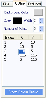
1. Change the background colour of the device 2. Change the outline colour and width 3. The Number of Points is is the number of items in the list. You can edit each of the points in the list 4. The Create Default Outline button creates an outline based on the position of the pins
|
Excluded Tab
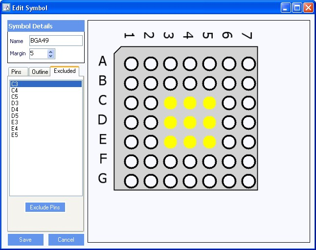 |
This tab lists the pins to be excluded on the device. These would normally be the pins that do not actually exist on the package.
b) To delete pins from the exclude list (ie, put them back on the device). Select the pins in the list (you can use CTRL and/or SHIFT to select multiple pins) then press Delete on the keyboard Once all the changes have been made, and the new Symbol name has been added, click Save to add the new Symbol to the library. |
Importing Parts
Import parts allows devices and Symbol files that have been created on another machine to be imported into the database without the need for the BSDL file. To import parts onto a second machine
1) Copy .part and .package files onto a memory stick to copy onto the new machine
2) Click “Import Parts” and then select the file to import. NOTE: do no copy the files into the database area on the new machine. They can be left on the memory stick. During the import process the software will create the files in the database area. Select all the files that need importing and click Open.