APEL Script Wizard Tutorial
This tutorial shows how the APEL Script wizard that is included in APEL Studio+ can be used to automatically generate the CHAIN and BUS sections of your APEL script. This is achieved in three easy steps
- Define the Scan Chain
- Creating the Buses
- Creating/Modifying the script
Syntax checks are also applied to the script allowing validation of existing scripts. These checks include
- Do all the devices have an Alias name?
- Are all of the Alias names unique?
- Are all of the Bus names unique?
- Do all the pins on the buses exist on the device chain?
- Are any of the pins on more than one bus?
- Does the specified package exist on the part?
- Do the part names exist in the Infinity Library?
Defining the Scan Chain
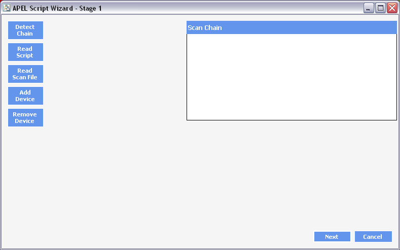
The first step to creating a script is to define the Scan Chain. There are four ways of generating the Scan chain
- Click Detect Chain to automatically detect the scan chain. This method requires that an AP-114 programmer is connected to your system and that the AP-114 is also connected to the target system. The power supply also needs to be connected to your target system.
- Click Read Script to read in an existing .APEL script.
- Click Read Scan File to read in an existing .APBS scan file created from Infinity SCAN. The scan chain defined in that Training data is imported into the APEL Script Wizard.
- Manually adding and deleting parts in the scan chain using Add Device and Remove Device.
Below we load in an existing script that contains the lines
CHAIN xc9536xl_cs48.CS48.MAIN, EPM3032AL44.PLCC44.SUPPORT
BUS GLEDPORT = {MAIN.PB01_11, MAIN.PB01_13, MAIN.PB01_15, MAIN.PB00_16, MAIN.PB00_14, MAIN.PB00_12, MAIN.PB00_10, MAIN.PB00_08, MAIN.PB00_05}
BUS RLEDPORT = {MAIN.PB01_10, MAIN.PB01_12, MAIN.PB01_14, MAIN.PB01_16, MAIN.PB00_15, MAIN.PB00_13, MAIN.PB00_11, MAIN.PB00_09, MAIN.PB00_07}
The lines above show that the CHAIN command has two devices (an XC9536XL and an EPM3032) and also has two buses (called GLEDPORT and RLEDPORT). We can see the scan chain defined in the example below
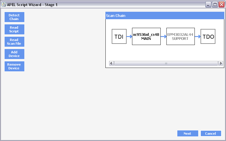
Once the Scan Chain is defined we can move onto the next stage. A scan chain must be defined at this stage. The devices must exist in the Infinity Part library to move on from this step however no validation is applied to the Alias name or the package definition at this stage.
It is possible to edit the device on the Scan Chain by double clicking on it. The following window will appear.
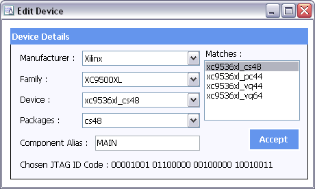
Here we can perform the following operations
- Change the device (including manufacturer and Device Family).
- Modify the package
- Change the Component Alias Name
The Matches Section gives a list of devices that have an identical JTAG ID and allows the device to be easily changed. It may be necessary to confirm the correct device if the Scan Chain has been automatically generated using the Detect Chain button. If more the one device matches the JTAG ID then you will be required to confirm the device selection before moving onto stage
Creating the Buses
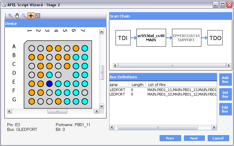
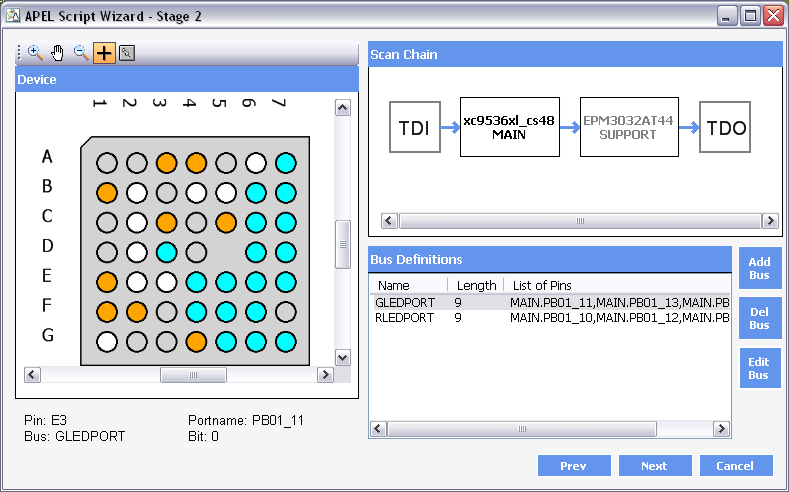
Stage 2 allows us to define the buses that can be used on the script. We can see in the screenshot below that the two buses defined in the script that was used in Stage 1 have now appeared in the list of bus definitions.
The following facilities are available at this stage.
- Clicking on a device in the Scan Chain will display that device in the Device window
- Double clicking on the device in the Scan Chain will allow the device to be edited in an identical way as Stage 1.
- The Device Window gives the following facilities.
- Zoom In/Out
- Pan (using the hand tool)
- View pin details (by selecting the Cross tool)
- Center the device.
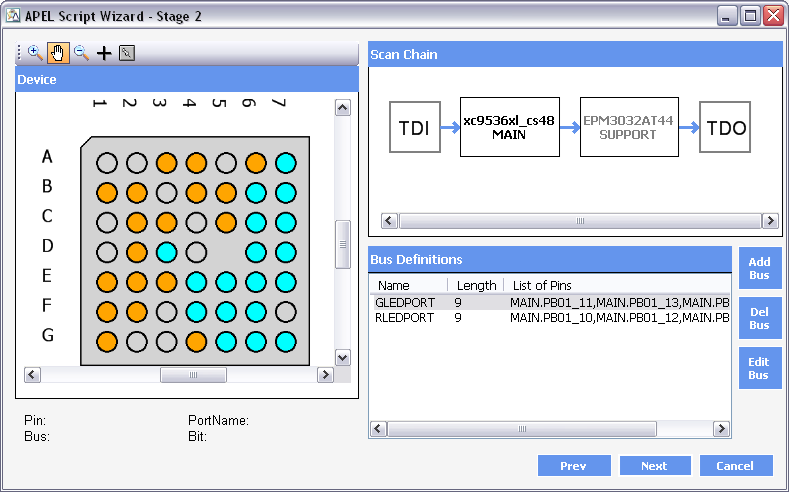
The bus definitions window shows the defined buses and allows buses to be added, deleted and edited. See Editing the Bus below
Here we can see the pin E3 has been selected. In this case the pin is used on the GLEDPORT bus and is bit 0.
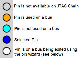
Device Window Colour Coding
The colours used in the Device window are defined below
Editing the Bus
There are two ways of editing/creating a bus. Manual editing allows the bus details to be entered into the table directly. The second way is to use the Pin Wizard. This allows the pins to be selected by clicking on the pin in the Device window. Buses are not restricted to one device and can be defined across all devices in the Scan Chain.
Manual Editing
The easiest way to edit the bus is to click on the list of pins and manually enter the bus definitions, see image below.
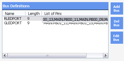
The Del Bus button will delete the selected bus in the Bus Definitions window. Both the Edit Bus and Add Bus buttons will bring up the select Pins window shown below. The only difference is that Edit Bus will load the existing bus details into the window.
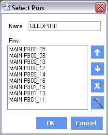 |
The list of pins defined for the bus are shown LSB first. To change the bit ordering you can use the UP and DOWN buttons. The X button allows individual bits of the bus to be deleted.
The final button is the PinWizard function. Details of this mode are given below. |
The list of pins defined for the bus are shown LSB first. To change the bit ordering you can use the UP and DOWN buttons. The X button allows individual bits of the bus to be deleted.
The final button is the PinWizard function. Details of this mode are given below.
Using the Pin Wizard
When clicking on the PinWizard Button on the Select Pins window, the PinWizard mode is entered. This causes all of the pins that are currently listed on the bus to go white.
- Clicking on an unused (cyan) pin will cause this pins to be added to the most significant bit of the bus and will turn the pin white.
- Clicking on a white pin will cause that pin to be removed from the bus and the pin will turn back to cyan.
- Clicking on an orange pin will have no affect as this pin is already used on another bus.
- Click on the PinWizard Button to leave PinWizard Mode.
Once all buses are defined then click Next to move to Stage 3. At this point all entries will be validated and any errors reported. These errors must be corrected before the wizard will let you move to Stage 3.
Creating the Script
Here we can choose to either create a new script or modify an existing one. If the initial Scan Chain was created by reading an existing APEL script, then the Stage 3 default will be “Modify Existing Script” and the default filename specified will be the original will be used. Otherwise the default will be to create a new script and the filename will be blank. Use Browse to specify the filename.
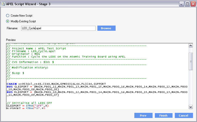
The Preview window allows you to
- View the script that will be created
- Make an alterations to the script before saving
Click Finish to save the file and quit the wizard.