Infinity SCAN Tutorial
Infinity SCAN is a graphical tool to perform boundary SCAN testing on PCBs. It differs from other similar tools in that there is no requirement to import a netlist or ‘understand’ the target platform. SCAN can learn about the board through training.
Configuring & Editing the JTAG scan chain
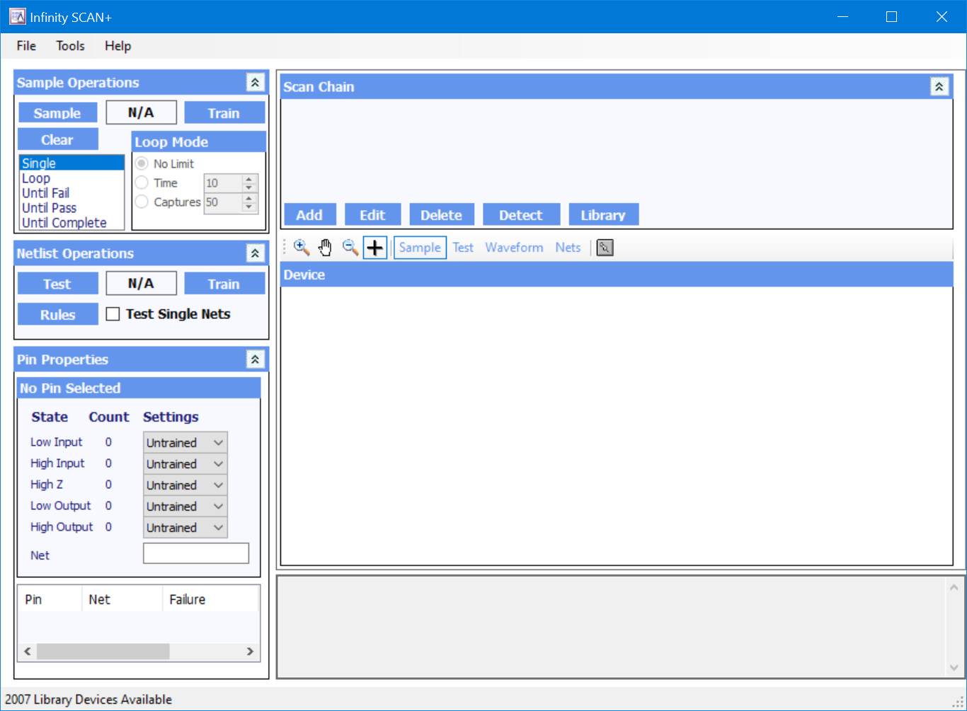
The first step in using Infinity SCAN is to set up the scan chain. The JTAG Scan Chain window is shown at the top of the screen. It represents the current configuration of devices in the Boundary Scan Chain on the target board. Before any results can be obtained by the Boundary Scan software, it is important that the Scan Chain is an accurate reflection of the devices on the board under test. If this has not been done then the software may send incorrect commands and misinterpret data received causing misleading and incorrect results.
Setting up the Scan Chain
When setting up a new board, the general steps involved are as follows:
- Connect the AP-114 to the target board and then apply power to the board.
- Attempt an automatic detection of devices on the board. In the majority of cases this will provide information about the number of devices on the board and their sequence in the boundary scan chain.
- Resolve any conflicts between potential devices and ensure that the correct package is selected for each device.
- Locate BSDL files for any unknown devices and add them to the device library.
- Update the scan chain with any new devices that have been added.
- Save the scan chain set-up in a Project File
This process may be iterative. In particular, if little is known about a board then it may not be possible to determine which devices will be present on the boundary scan chain in order to determine if they need to be added to the Infinity Database library.
Setting up the Scan Chain for the Atomic Training Platform
As an example of the process, setting up the scan chain for the Atomic Training Platform is performed as follows:
Step 1: Start the software
The AP-114 is connected to the JTAG connector on the Training Platform. Power is applied to the training board via the USB port.
Running Infinity SCAN opens the boundary scan instrument and shows an empty scan chain.
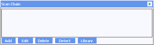
Step 2: Automatic detection
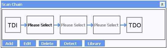
Select DETECT to attempt an automatic detection of devices on the board. Usually this will provide information about the number of devices on the board and their sequence in the scan chain. As package information is not usually available from the electronic signature of the device, the specific device name will almost always be required to be selected manually. This is the case with the Training Platform.
Step 3: Editing the details
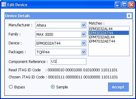
Simply click on the device to bring up the EDIT DEVICE window:
Each of the devices are available in several different packages all of which share the same ID code. Inspect the board to determine which of the available versions is fitted allows the correct entry to be chosen from the Recommended Matches.
It is important that the correct package is selected in order that the correct pin results can be displayed.
Optionally assign a component reference to each device. This allows an operator to quickly identify a device on the board from its entry in the chain. This can be done during step 3 or any time afterwards. After references have been added for the training board, the scan chain will show them in each entry.
Then select Sample for the device to be included within the Scan Chain, or Bypass to remove the selected part from the Scan Chain. A device that is bypassed will not return boundary scan results speeding up data acquisition for remaining items in the chain. This can be useful if only one or two devices in the chain are of interest and will allow results from other devices to be ignored. As with the Component reference, this can be changed at any time by double-clicking on the device, or selecting and clicking on EDIT.
Repeat the above steps all devices within the chain.
Step 4: Manually adding devices (if required)
With the Test Platform, all devices on the scan chain are already present in the library. If it is necessary to add devices then click on ADD, locate the appropriate BSDL files and add them to the device library. Alternatively, follow instructions in the Infinity Database Appendix and edit the associated entry in the scan chain.
Step 5: Save the project
You can now save the scan chain set-up to a Boundary Scan Project File using FILE > SAVE PROJECT AS. When saving a file, the details of the devices in the scan chain and their component references are automatically stored along with any other comparison information. This allows details about a board to be quickly and easily stored, and then recalled, as necessary.
Boundary Scan Operations
The AP-114 monitors the state of the pins on devices in the boundary scan chain in their active configuration. This allows a real-time snapshot of all of the pins to be captured and investigated without requiring detailed knowledge of the board under test. However, it is important to understand that the capture process is statistical and may not capture every possible state. For example, consider the following diagram:
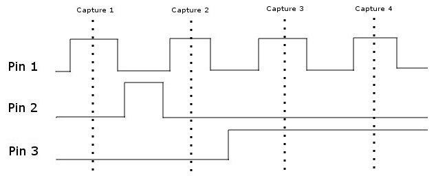
This shows four individual captures occurring one after the other for three pins. The time between captures depends on a number of factors including the number of devices on the boundary scan chain, the number of devices in bypass, the complexity of the devices and the speed of the computer being used. With the capture timing shown above, it will appear to the software that Pin 1 is always high and that Pin 2 is always low. In practice this is a highly exaggerated situation and in the majority of cases all pin states will normally be seen within a few seconds. However, it does highlight how important it is to allow enough time/captures to ensure reliable data is extracted from the target board.
Sample
The Sample function allows data to be acquired from the AP-114 JTAG interface. The AP-114 can be configured to acquire data for different periods of time. This can be adjusted according to your specific requirements.
The following sample modes are available:
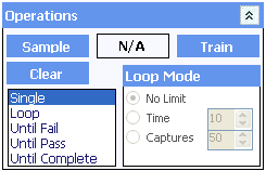 |
Single: A single capture of the pins is taken, acquisition stops immediately after this has completed. Loop: Capture of pins occurs on a continuous basis until terminated by the operator or the Read Limit is reached, according to the Loop Mode Until Fail: Capture of pins occurs until the overall capture result fails. This is useful for capturing intermittent failures that may only occur after an extended period of time. Until Pass: Capture of pins occurs until the overall capture result passes on all pins. A pin failure will not stop capture - but the overall result will remain as Fail. Until Complete: This is similar to Until Pass but a pin failure will immediately stop capture. |
The Until Fail, Until Pass and Until Complete modes of capture are only effective after training has been completed. See Automatic Training for more information.
The Until Complete mode of operation is particularly useful for ensuring that the pins on a board have been seen at all expected logic levels. For example, by setting the input high and input low states for a clock pin to Ensure the capture will not complete until both states have been seen at least once. A board in this situation where the clock is not connected or which is shorted to one or the other power rails will not pass - even though both states are valid.
Loop Mode
The Sample Limit allows a sample operation to finish before a condition is met. The sample operation can be set to:
- No Limit: Sampling will only terminate once the condition has been met. For Loop captures the read operation will continue until the operator stops the capture.
- Time (s): Sampling will terminate when either the specified number of seconds has elapsed or the condition has been met.
- Captures: Sampling will terminate after the specified number of captures have been taken.
The speed of capture depends on a number of factors including the number of devices on the scan chain, how many have been put into bypass and the speed of the computer running the software. In some situations, it may be preferable to ensure that at least a certain number of states have been seen regardless of the speed of acquisitions - in which case the Captures limit would be appropriate. In other situations, it may be sufficient to wait a certain period of time - particularly where the acquisition rate is high enough to warrant it.
Training & Comparisons
A powerful aspect of the JTAG boundary scan testing is the ability to monitor devices on a board and compare this information at a later point in time. Although expected results can be trained for each pin individually, it is usually more convenient to perform some automatic or manual bulk training first and then perform any minor adjustments.
 |
Training and comparison information is shown in the Pin Properties section. There are two ways of looking at specific pin information. In the Device Window, simply click on the pin you wish to look at. Alternatively, once a sample loop has resulted in a failed state, then the list of failed pins is displayed in the Pin Properties window. Simply click on each failed pin to see the Pin Details. This will also switch to the correct device in the Device Window if appropriate. This allows bulk training to be accessed, shows details for a selected pin and shows any comparison failures. |
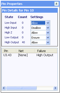
Pin Properties
Each pin on a boundary scan device can be either an input to the device or an output from the device. In addition, the level on each pin can be either a logic high or a logic low. This means that there are five possible states for any one pin:
- Low Input - The device is reading from the pin and it is currently at a low logic level
- High Input - The device is reading from the pin and it is currently at a high logic level
- Low Output - The device is driving the pin to a low logic level
- High Output - The device is driving the pin to a high logic level
- High Z - This state occurs when the output enabled has been disabled inside the device and it does not contain any logic for input mode so the pins cannot be read
Not every pin will contain electronics to support all states. For example, a pin which is always a clock input may not contain any circuitry within the device to allow that pin to drive any external signals so will only support Low Input and High Input states. Similarly, a pin which is always an output will never show the Low Input or High Input states.
The pin details section shows a count for each of the four possible states and an associated comparison setting for that state. There are four possible comparison settings that can be shown:
- Untrained - No training has yet been performed on this pin either manually or automatically. If any one state for a pin shows Untrained then all states for that pin will show Untrained.
- Allow - The state for this pin is allowed and counts towards an overall comparison pass.
- Disallow - The state for this pin is not allowed and will give an immediate comparison failure for the pin, the device and the overall result.
- Ensure - This is similar to Allow but the comparison will not pass until this state has been seen at least once.
The pin will fail if the AP-114 sees it in the low input or high input state as both states are set to Disallow. Any comparison for the pin will pass if either the high output or low output states are seen - but the pin will not be Complete until the pin has been seen in the low output state at least once.
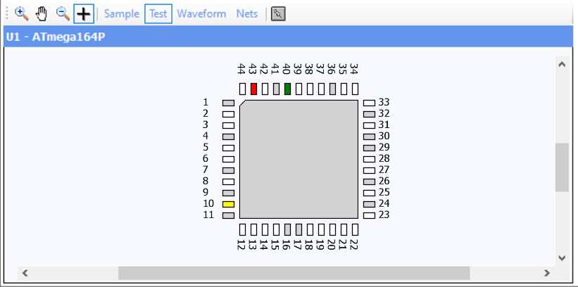
Device Information
The Graphical Pin Display in the Device Window provides a quick and easy method for viewing information about all pins of a selected device in the JTAG scan chain.
The display shown above is a typical example of a TQFP device on the boundary scan chain. Not all pins have information that can be captured using the JTAG boundary scan chain. These pins are known as 'linkage' pins and are typically pins such as power supply pins, analogue pins or pins used for the JTAG interface itself. In the Graphical Pin Display, these are shown as grey pins and no results will be shown for these pins.
Clicking on any individual pin shows its specific properties in the Pin Properties window.
Color Code Key
There are two different display modes in SCAN. These as SAMPLE Mode that displays the current status of each pin and TEST Mode that shows the pin test comparison states.
SCAN uses a color coded system to display the state of each pin. The default colors are shown below. The colors can be changed by clicking on the color.
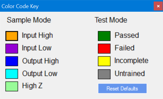
Sample Mode
During Training and Sample operations, each pin may be in one of four states:
|
Low Input |
The device is reading from the pin and it is currently at a low logic level. This is shown as Violet |
|
High Input |
The device is reading from the pin and it is currently at a high logic level. This is shown as Orange |
|
Low Output |
The device is driving the pin to a low logic level. This is shown as a Cyan |
|
High Output |
The device is driving the pin to a high logic level. This is shown as Blue |
The results are updated immediately following an acquisition. In loop mode, the state of pins that are changing will update after each individual acquisition is performed.
Test Mode
When training has been performed, this section allows the results of the pin comparisons for entries in the scan chain to be quickly investigated.
In addition to the 'linkage' pins, which are shown in grey, there are four possible conditions for each pin:
|
Untrained Pins |
These are pins that could be trained but have no training on them. These pins are shown in white |
|
Comparison Pass |
These are pins that have passed the conditions associated with that pin. These pins are shown in green |
|
Comparison Fail |
These are pins that have failed the conditions associated with that pin. These pins are shown in red |
|
Incomplete Pins |
These are pins that have not completed the conditions associated with that pin. These pins are shown in yellow |
Comparison Results
In addition to the detailed pin information, the boundary scan chain window above displays a top-level summary of the comparison results for devices on the scan chain.
In the example shown here, U3 has at least one pin failing and is shown in red. All relevant pins of U2 have met all required conditions, and has passed. U1 has at least one pin that has not completed comparisons and is shown in yellow.
Automatic Training
Although as mentioned previously the states for each pin can be configured manually, it is usually more efficient to perform training on many pins at once. Pressing the Train button displays the training window:
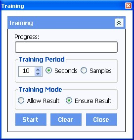
The Training window has the following functions
Clear Training
This allows any existing training results to be cleared. In effect it will set every state for every pin of the devices on the boundary scan chain to 'Untrained'. This is useful to remove any old training information before starting a new training session.
Training Mode
The Automated Training is done by performing a sequence of reads automatically and updating the comparison states. This can also be done several times to allow learned results to be combined. The default learning time is set to 10 seconds but this can be increased to a maximum of 60 seconds or the training can be performed several times. It is also possible to train for a pre-fined number of samples. Comparison settings and results are shown on the main device window.
The results can be set to either Allow or Ensure. This is done by setting the required radio button.
The Allow result button will change the pin states of device pins to allow any results that have been seen in the last read operation. This is done cumulatively to allow the state of the board to be trained multiple times without affecting previous results. Pressing Ensure result has the same effect as Allow result but the results are changed to Ensure instead of Allow.
Press Start to begin the automatic training operation. The training time is specified by the learn time parameter. Automatic training will last this period regardless of how many captures are taken during this time.
Note: It is important to understand when considering training that the capture of data over the boundary scan chain when monitoring device operations is a statistical one. See the section Boundary Scan Operations section for more information.
Once the software has been successfully trained, and each pin has been assigned the relevant properties and required test states, then all of the settings can be stored for future use, and Production Mode testing. Select FILE > SAVE PROJECT AS. Store the file in the required location. It will be saved with a .apbs file extension. To recall a Project file, simply select FILE > OPEN PROJECT. The JTAG Scan Chain, and all the training and pin information will be loaded ready for testing.
Infinity Database
APEL uses the Infinity Database. See Database for more information